Intro
Welcome to Part 5 of the NSX-T Lab Series. In the previous post, we covered adding/removing additional NSX Managers and forming a cluster.
In this post we’ll cover the creation of IP Pools for the host TEP’s.
What is an IP Pool?
As per the VMware documentation: Tunnel endpoints are the source and destination IP addresses used in the external IP header to identify the hypervisor hosts originating and end the NSX-T Data Center encapsulation of overlay frames.
IP Pools are used to assign the TEP’s to transport nodes which are either the hosts or the edge nodes. The IP Pool can be either DHCP or static, for simplicity we’ll use static IP Pools for this lab build.
Typically DHCP was used in NSX-V for Metro cluster builds where there was technically only one site so only one pool but the VTEP’s at each site while needing to have the same VLAN ID had to be in different subnets so a local DHCP server would be setup at each site to assign the site local IP subnets.
Each transport node requires a Tunnel EndPoint (TEP) not a VTEP as thats VXLAN and not GTEP which would have made sense for Geneve but hey we’ll go with TEP.
Dependant on the configuration of the transport nodes uplink profile (which we will cover in two posts time) a host will typically have one or two TEP IP’s assigned, except for KVM hosts where failover order is the only supported model which results in a single TEP.
The IP pool is simply a construct that holds a list of IP addresses ready to assign to the transport nodes.
Multiple IP Pools can be created and if for example you were building a collapsed cluster deployment where edge and compute are running on the same hosts and that host only had two physical uplinks then the Edge and compute nodes must reside on the same N-VDS and as such a different VLAN / subnet is needed for the edge and compute node TEPs.
If the host transport node has four physical NIC’s, multiple virtual switches can be configured, for example, one vSphere distributed switch or a vSphere standard switch would be used for the Edge Nodes with two of the NICs the other two NIC’s would be assigned to an N-VDS and used by the compute workload.
In this configuration the Edge node TEPs and the compute TEPs can be in the same VLAN.
I’ll cover this in more detail in another post but for now lets get on with the lab build.
The build
From the NSX console select the ‘Networking’ page then ‘IP Address Management’ and finally ‘IP Address Pools’
Then ‘Add IP Address Pool’

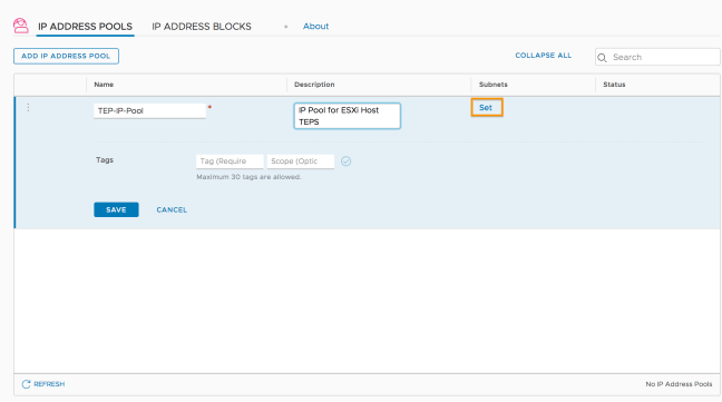
Give the Pool a name then click on the ‘Set’ option under Subnets

When we click on ‘Add Subnet’ we are presented with two options.
IP Block and IP Ranges.
IP blocks are used by NSX Container Plug-in (NCP). For more info about NCP, see the NSX Container Plug-in for Kubernetes and Cloud Foundry – Installation and Administration Guide.
IP Ranges is what wee need for our TEPs so go ahead and select that option.

Add the IP range the CIDR and the gateway IP then hit ‘Add’

If needed additional subnets can be added but normally we would create a new pool if we needed additional subnets so lets hit ‘Apply’

The IP Pool is added and we are done.

A nice easy configuration next we need to setup our transport zones.
NSX-T Lab Part:6 NSX-T Transport Zones
