
Intro
Introduced in NSX-T 3.0 is VRF lite also known as VRF Gateway, VRF or Virtual Routing and Forwarding allows multiple instances of routing tables to exist within the same gateway at the same time. Essentially this gives us a multi tenant routing solution using a single parent T0 gateway. As a result we can utilize a single Edge cluster with say two Edge nodes to provide isolated routing and forwarding for up to 100 VRFs.
To achieve that with normal T0 gateways you’d need a minimum of 100 Edge nodes (one for each tenant) and 200 Edge nodes to get redundancy for each.
Features and Characteristics
- Each VRF maintains its own Routing and Forwarding tables.
- A VRF acts as a virtual Tier-0 Gateway configured under a ‘Parent’ Tier-0 Gateway.
- VRF gateways are deployed as Tier-0 gateways.
- VLAN tagging can be used in the uplink trunk segments that connect with the external devices to separate the VRFs.
- Tenant Segments can be connected directly to the VRF Tier-0 (single-tier topology) or to the tenant Tier-1 (multi-tier topology).
- Inter-VRF traffic is either routed through the physical fabric or can be configured to be direct by using static routes.
- Routing between VRFs happens in the physical layer by default.
- By configuring route leaking, traffic can be exchanged between VRF instances without going to the physical layer. However, that requires multi-tier topology, where each tenant is connected to a dedicated Tier-1 gateway.
Requirements
- VRF’s must be linked to a parent Tier-0 gateway.
- Deploy at least one Edge VM or Bare Metal appliance (ideally two for redundancy).
- Create an Edge Cluster and add the Edge VM/s or BM appliance/s to the cluster.
- Create a Parent T0 in the networking section.
- Either tagged segments or Trunk Segments are required as the uplink interfaces on the Edge VM’s. When using trunks each VRF created will consume a VLAN on the trunk between the T0 and the ToR based on the number of Edge uplinks.
- The VLANs used in the uplink interfaces of the Parent T0 should not overlap with any of the VRF networks.
Caveats
- VRF, as a child object, inherits multiple properties from its parent Tier-0 gateway:
- Failover mode (HA Mode)
- Edge cluster
- Internal transit subnet
- T0-T1 transit subnet
- BGP AS number
- Graceful Restart Settings
- BGP multipath Relax Settings
- Edge node bandwidth is shared across all Tier-0 Gateways and VRFs.
- VRF is not supported on stretched Tier-0 gateways in NSX-T Federation.
Starting setup.
Shown below is my starting setup I have a single Tier 0 Gateway deployed and connected to the T0 is a single Tier 1 Gateway.
Connected to the T1 I have several tenant networks these are split across the Blue and Red tenants.
- DCA-Web-Blue
- DCA-App-Blue
- DCA-DB-Blue
- DCA-Web-Red
- DCA-APP-Red
- DCA-DB-Red

Logical view.

I have my parent T0 in this case DCA-T0 setup and using the DCA-Edge-Cluster which consists of two Edge Nodes.

Each edge node is dual homed for ECMP to the physical network.

BGP routing has been setup. In this setup I have configured the BGP neighbors on the parent T0.

The End Goal
Shown below is the end goal, we want to configure tenant separation so that each group of tenant segments have isolation and a dedicated routing domain within their own VRF. To achieve this we will configure a Blue VRF and a Red VRF and then migrate the VM segments to the corresponding T1 Gateway.

To Trunk or Not to Trunk
OK first things first before we get started with deploying the VRF T0’s we need to configure some interfaces to use for the uplinks. There are a couple of ways to do this Trunked or Non Trunked.
Non Trunked
What do I mean by Non trunked? Essentially setting up the Uplink segments the same way that you would for a normal T0. This is perfectly acceptable and works just fine each uplink segment is tagged with a VLAN ID and associated with the relevant named teaming policy for the given Edge uplink 1 or 2. However this setup requires a new segment for each VRF Edge Uplink so for a dual Edge uplink configuration thats two segments needed per VRF. Given that we can scale a single Edge cluster to 100 VRF’s we’d need up to 200 Uplink segments to build this.
Isn’t there a more scalable way to do this? Funny you should ask….
Trunked
We can achieve the same result but instead of having 200 NSX-T Uplink segments we can do it with just 2!
We will configure a VRF-Trunk-A Segment and configure it with a VLAN range to allow the Edge node Uplink 1 to connect to the Top of Rack Switch 1, in my build I’ll be using VLANs 214-215.
We will also configure VRF-Trunk-B and configure it with a VLAN range to allow the Edge node Uplink 2 to connect to the Top of Rack Switch 2, in my build I’ll be using VLANs 224-225.
The VLAN range can be larger of course however it must not include and TEP VLAN’s or any existing VLAN ranges on other Segments. This last part is key and I’ve noticed that on a lot of VRF blog posts the information here is out of date. For example the general information here is to configure two trunk segments trunking either all VLAN’s or a range of VLAN’s which are the same across the two segments.
Trunking all VLAN’s is a big no no as the TEP VLAN’s should not be part of the range.
Trunking the same VLANs across both trunk segments also will not work and here is why.
Most blogs on this are based on version 3.0 and in version 3.0 there wasn’t a mechanism for NSX-T to check for overlapping VLAN IDs, thats no longer the case and as such the NSX-T segment may fail to initialize if the ranges overlap.
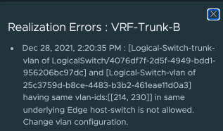
This can be seen below, I have my two trunk segments each with VLAN Ranges 214-230 the first segment created just fine however the second has a Failed error message.

If click on Failed we can see the reason. Having the same VLAN-IDs in the same underlying Edge host-switch is not allowed. The main issue with this error is that you won’t get it if you just create two trunk ports with the same VLAN ranges, NSX-T will allow you to do that however when the T0 is configured to use these segments you will get issues. I managed to generate the error but changing the trunk range to overlap after added my VRF T0 so best to just avoid the issue and not use overlapping VLAN IDs across the two segments in the first place.
The Build
Trunk Interfaces
As mentioned above for a scalable solution you should use trunk interfaces so thats what I will cover in this blog post, I will create two trunk interfaces for use by the Edge node uplinks 1 and 2.
I’m deploying this on NSX-T 3.2 so the menus may be in a slightly different place on your system.
Navigate to Networking, Segments then click Add Segment

Give it a Name and set the VLAN Transport Zone, now select the Uplink Teaming Policy for Uplink 1 and then set the VLAN range. Click SAVE

Repeat for the second trunk interface using the other VLAN range.

VRF Blue
We can now create our first VRF for the Blue tenant.
Navigate to Networking, Tier-0 Gateways now click ADD GATEWAY and select VRF

Enter a Name then select the Connect to Tier-0 Gateway, you will notice that the HA mode is automatically configured as is the Edge cluster remember these settings come from the Parent T0 and cannot be changed on the VRF. Now click SAVE then select Yes to continue configuring the T0.

Expand interfaces and click Set. We now need to add in the uplink interfaces for the Blue T0 for this I am using VLANs 214 for uplink 1 and 224 for Uplink 2.
Click ADD INTERFACE give it a Name set the IP Address / Mask then select the Trunk-A as the Connected To (Segment) Next select the first Edge Node Set the URPF Mode to None if you need to and this is the important bit set the Access VLAN ID in my case 214 which is for the Blue VRF tenant (remember 215 will be used for the Red Tenant) Note that you can see the list of available VLAN IDs assigned to the Segment from which you can pick. Click SAVE

Repeat for the Uplink 2 on Edge Node 1. Note the use of the Trunk B segment and VLAN 224 this time.

Now repeat for the uplinks for your remaining Edge Nodes.
If you accidentally try and set an Access VLAN ID which is not part of the Trunk you will get an error message so you cannot actually proceed with an incorrect configuration.

We now have our VRF Blue interfaces setup go ahead and click CLOSE

The Next step is to setup our BGP routing. Expand BGP, now toggle BGP On and click SAVE.
Notice how the Local AS cannot be changed as it comes from the Parent T0 also Inter SR cannot be enabled.
Now click Set next to BGP Neighbors

Click ADD BGP NEIGHBOR and configure BGP how you normally would to your physical network for a multi tenant solution. For my lab I’ll be using the same Remote ASN for all neighbors for simplicity.

I now have my VRF blue BGP neighbors configured.

Next expand Route Redistribution and click Set

Again configure this how you normally would for a T0 Gateway. Then Apply this and click SAVE on the T0.

VRF Red
Thats the Blue VRF configured now repeat the process for the Red VRF this time using the Red tenant uplink VLANs for me thats 215 and 225.


T1 and VM Segment Configuration / Changes
Now that I have my two tenant VRF T0’s I need to add a new T1 for Red and reconfigure my existing T1 to be for the Blue tenant.
T1 Red
I’ll start off with the T1 Red this will allow me to move the existing VM Overlay segments to it and establish routing via the red VRF T0.
If you are doing this in a live production environment then you should first check your BGP peering is working correctly from the physical to the VRF T0’s before making any changes to the existing VM segments so as not to loose connectivity for too long during the change.
Navigate to Networking, Tier-1 Gateways and click ADD TIER-1 GATEWAY

Enter a Name and select the correct VRF T0 in this case VRF-Red-T0 then click SAVE
You can ignore the HA Mode this will change to Not Set once I save it as my T0 is Active-Active.

Now expand Route Advertisement and configure the options that you want to redistribute to your T0 VRF. Then click SAVE.

The final step for the Red tenant is to move the Red NSX-T Overlay segments to the new Red T1.
Navigate to Networking, Segments and edit your existing Red segments and change the connected T1 to the new Red-T1.

T1 Blue
This one is simple I just need to rename the T1 and connect it to the Blue VRF T0
Navigate to Networking, Tier-1 Gateways Now find the existing T1 and click the Ellipsis and select Edit.
Again If you are doing this in a live production environment then you should first check your BGP peering is working correctly from the physical to the VRF T0’s and make any changes to the existing VM segments so as not to loose connectivity for too long during the change.

Simply rename the T1 and change the connected T0 to VRF Blue

There is no need to make any changes to the blue segments they are still connected to the same original T1 its just got a new name which will automatically be updated on the segment page.

Our topology now looks like this.


Final Testing
If we take a look at one of the Edge nodes we can see the DR and SR components for the Parent T0 and the VRF Blue and Red T0’s.

Lets take a look at the routes coming from the blue VRF SR note the 10.100.1.0, 10.100.2.0 and 10.100.3.0 networks these are the Blue Web, App and DB Segments.

Looking at the VRF Red SR routes note the 10.110.1.0, 10.110.2.0 and 10.110.3.0 networks these are the Red Web, App and DB Segments.

From one of the ToR switches we see the same networks coming from the relevant Uplink VLANs on the Edge Node.
10.100.1.0, 10.100.2.0 and 10.100.3.0 via 10.214.1.11 and 12 which is the Blue VRF
10.110.1.0, 10.110.2.0 and 10.110.3.0 via 10.215.1.11 and 12 which is the Red VRF

Finally lets do a trace from an external PC to a VM on the Blue Web segment 10.100.1.0
Again it hits the 10.214.1.11 interface.
traceroute to 10.100.1.11 (10.100.1.11), 64 hops max, 52 byte packets
 1  192.168.10.1 (192.168.10.1)  1.348 ms  1.015 ms  2.119 ms
 2  192.168.10.252 (192.168.10.252)  0.421 ms  0.506 ms  0.393 ms
 3  10.200.1.2 (10.200.1.2)  0.543 ms  0.530 ms  0.482 ms
 4  10.214.1.11 (10.214.1.11)  0.888 ms  0.786 ms  0.767 ms
 5  100.64.16.1 (100.64.16.1)  0.712 ms  0.753 ms  0.692 ms
 6  10.100.1.11 (10.100.1.11)  2.082 ms  2.185 ms  1.728 ms
And now just to be different to the Red App Segment 10.110.2.0
We now hit the 10.215.1.11 interface.
 1  192.168.10.1 (192.168.10.1)  2.415 ms  2.741 ms *
 2  192.168.10.252 (192.168.10.252)  0.778 ms  0.464 ms  0.392 ms
 3  10.200.1.2 (10.200.1.2)  0.583 ms  0.594 ms  0.564 ms
 4  10.215.1.11 (10.215.1.11)  1.028 ms  1.548 ms  1.211 ms
 5  100.64.176.1 (100.64.176.1)  3.635 ms  1.409 ms  0.889 ms
 6  10.110.2.1 (10.110.2.1)  3002.336 ms !H  3051.443 ms !H  3002.301 ms !H
And with that we are done 🙂
Thank you for your clarification.
I need the configuration on the ToR swich please.